Energy system integration
PV, Energy Storage and EV Charging Test Architecture
This architecture treats the EV charger as one subsystem in a wider photovoltaic, storage and grid-connected energy flow. The project team must define operating scenarios, control ownership, power ratings, facility limits and evidence for each subsystem before selecting programmable sources, loads and charger interface equipment.
Reference application architecture
Who this workflow is for
- ✓ Commercial and industrial energy project teams
- ✓ Power electronics and microgrid laboratories
- ✓ Charging infrastructure system integrators
Engineering objectives
- ✓ Exercise coordinated energy-flow scenarios under controlled conditions
- ✓ Separate charger-interface behavior from site energy-management behavior
- ✓ Record commands, setpoints and measured power at system boundaries
Reference system configuration
Final ratings, instruments, options and facility interfaces must be agreed against the actual test plan.
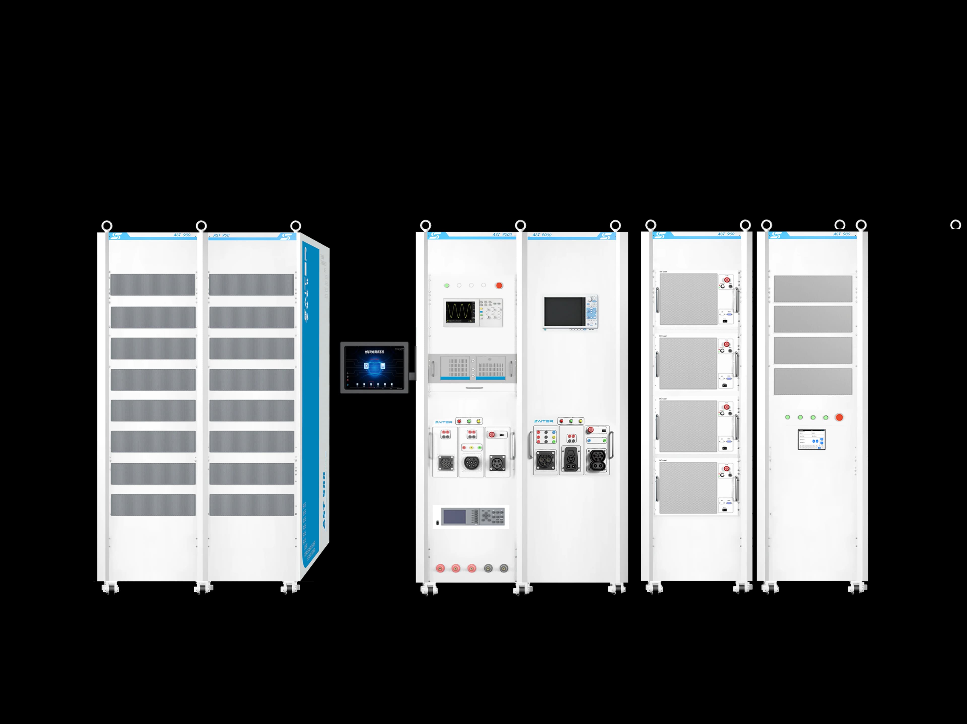
Charger interface and protocol test system
Represents the selected vehicle-side charging workflow and records charger communication and output.
Programmable source and grid simulation
Reproduces the supply conditions and operating envelope defined by the energy-system test plan.
Storage and load path
Absorbs, returns or redirects energy according to the specified ratings, controls and facility permissions.
Supervisory measurement and control
Aligns energy-management commands with charger, storage, grid and load measurements.
Suggested execution workflow
- 1
Draw the power and control boundary
Identify every source, storage device, converter, charger, load, controller and measurement point.
- 2
Define operating scenarios
Specify initial state, energy priority, setpoints, transitions, limits and expected protective behavior.
- 3
Validate subsystems first
Establish stable charger and power-equipment baselines before testing coordinated control.
- 4
Run controlled transitions
Change one operating condition at a time and synchronize commands with measured power and charger state.
- 5
Review energy and protection evidence
Confirm that observed flows, limits, alarms and shutdown behavior match the approved project procedure.
Expected project outputs
- ✓ System boundary and responsibility diagram
- ✓ Scenario matrix with initial states and limits
- ✓ Synchronized control and measurement record
- ✓ Findings separated by charger, storage, grid and supervisory subsystem
Confirm before configuration
- ✓ Power ratings and bidirectional requirements
- ✓ Grid-connection and regeneration permissions
- ✓ Energy-management interfaces and control ownership
- ✓ Protection, measurement accuracy and report requirements
Relevant equipment
Configure this workflow for your project
Share the charger interface, standards, electrical range, test environment and evidence requirements with an APEX engineer.
Talk to an engineer