DC Charger Testing / Laboratory Testing / Field Service
ST-HCDC-HPC
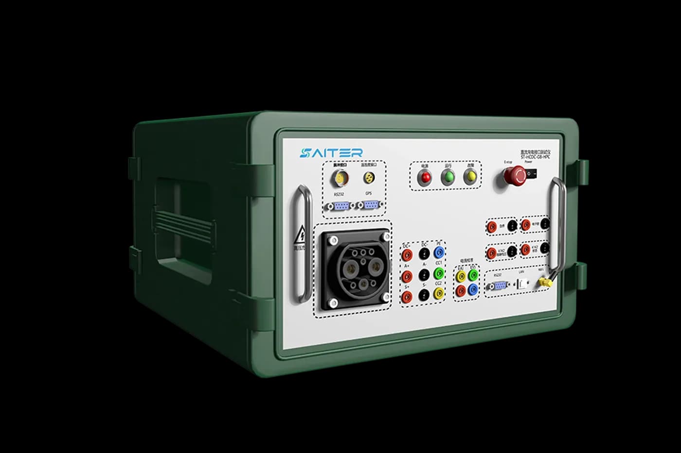
High-Power DC EV Charger Comprehensive Tester
Portable high-power DC charger test system for laboratory, production and field-service validation, with GB/T protocol analysis, BMS simulation, metering verification and external-load testing.
Product Overview
High-Power DC EV Charger Comprehensive Tester
ST-HCDC-HPC is a third-party field test system for non-vehicle conductive EV chargers. Built around GB/T 27930-2015, GB/T 34658-2017 and GB/T 34657.1-2017, it replaces test vehicles for repeatable charger validation, avoiding incomplete coverage, battery wear from repeated charging and potential vehicle damage caused by charger faults. The system supports R&D debugging, metering verification and end-of-line testing for charger manufacturers, laboratories and charging facilities.
Use ST-HCDC-HPC when a repeatable instrument must replace a vehicle during high-power GB/T charger development, factory acceptance or field diagnosis. It combines charger communication, battery-voltage simulation, measurement access and fault simulation in a portable system.
Choose the right test configuration
Interface and workflow
GB/T DC charger communication, insulation-fault and metering workflows. Review the listed 2015/2017 reference standards against the revision required by your project.
External load and connection limits
No built-in load; external load connection up to 250 A. The 0–1100 V battery simulator has a 20 mA maximum output and is not a high-power battery source. The Hall sensor range does not determine load-path current.
Options and accessories
PC software is included. Confirm optional BMS communication and high-speed waveform modules, measurement connections and the cables needed by your procedure.
Procurement checklist
Confirm the delivered configuration before ordering
Interface and standards
Confirm the connector, market, protocol and exact standard editions required by the charger and test plan.
Electrical and load path
Separate socket, cable and measurement ratings from the source or external load used during sustained power tests.
Evidence and options
List required metering accuracy, message or waveform capture, fault cases, report fields and optional modules.
Acceptance and support
Agree supplied accessories, software, factory acceptance checks, commissioning, training and support boundaries.
Key Features
Designed for reliable EV charger validation.
- 01Built-in battery-voltage simulation from DC 0 to 1100 V continuously adjustable, with a 20 mA maximum output, R4 resistance simulation and U2 pull-up-voltage simulation at two test points.
- 02Built-in 0.1% high-precision Hall current transformer covering 10-1000 A, with both voltage-type and current-type test interfaces for multiple calibration methods.
- 03PC software exports and parses test messages, monitors charger data in real time, supports abnormal-state diagnosis and generates GB/T 34658-2017 protocol conformance reports.
- 04Simulates BMS-to-charger communication across handshake, parameter configuration, charging and charge-completion stages. Optional BMS communication and high-speed waveform acquisition modules support plug-in testing.
- 05Eight selectable resistance levels provide insulation-fault simulation for insulation-monitoring function tests.
- 06External high-power load terminals make it possible to connect a separate load for partial NBT 33008.1-2018 load-test items. The tester has no built-in load and supports an external load up to 250 A.
- 07Modular, easy to integrate and suitable for field use, with a protective design and total weight no greater than 25 kg.
Technical Specifications
Core specifications
| Test Object | Non-vehicle conductive DC charger |
|---|---|
| Connector Socket Count | 1 |
| R4 Equivalent Resistance | 200-11,000 ohm, 1 ohm step |
| Voltage / Current Sampling | ±0.5% RD; voltage 200-1000 V; current 10-300 A |
| Working Power | 100-240 VAC, 50 Hz; 35 W |
| Communication Interfaces | LAN, RS232, Wi-Fi |
| External Load | No built-in load; external load up to 250 A |
| Dimensions | L561 x W455 x H265 mm |
| PC Software | Included |
| Operating Environment | Operating: -20 to 50 °C; storage: -30 to 70 °C; relative humidity: 90% (10-30 °C), ≤75% (30-40 °C), 45% (40-50 °C) |
| Reference Standards | GB/T 18487.1-2015; GB/T 20234.1-2015; GB/T 20234.4-2022; GB/T 27930-2015; GB/T 34658-2017; GB/T 34657.1-2017 |
Need this model configured for your charger?
Send the connector, target standard, voltage/current range and test workflow. The form below already includes ST-HCDC-HPC as the inquiry context.
Request a configuration reviewApplication Scenarios
Where this product is used
Product FAQ
Common questions about ST-HCDC-HPC
Does ST-HCDC-HPC contain a high-power load?
No. It provides terminals for a separate load and supports an external load connection up to 250 A.
Which DC charger workflows does it support?
It supports GB/T protocol analysis, BMS simulation, insulation-fault checks, metering verification and selected external-load tests.
Can it be used outside a laboratory?
Yes. The portable enclosure and included PC software support factory, commissioning and field-service workflows.
Does the battery simulator or Hall sensor define high-power capability?
No. The battery-voltage simulator outputs a maximum of 20 mA, and the Hall sensor measurement range is separate from the power path. Sustained charging tests require a compatible external load within the listed 250 A connection limit.
Reference application architectures
See how this equipment can fit into a laboratory, production or field workflow. Final configuration depends on the actual test scope.
Integrated EV Charger Validation Laboratory Architecture →
A reference architecture for coordinating charger interfaces, programmable power equipment, protocol analysis and traceable laboratory evidence.
EVSE Production End-of-Line and Aging Test Architecture →
A modular production architecture for repeatable charger identity, functional, communication and power checks with traceable result handling.
PV, Energy Storage and EV Charging Test Architecture →
A project-planning architecture for coordinating photovoltaic generation, storage, grid conditions and DC charging tests without obscuring subsystem responsibilities.
Inquiry Form
Request pricing, lead time or technical support.
Include your target standard, voltage/current range and testing environment for a faster recommendation.