DC Charger Testing / Laboratory Testing
AST-9000
Multi-Standard DC EV Charger R&D Test System
Integrated GB, European and North American DC charger R&D system with battery simulation, BMS communication, CAN capture, programmable sources and automated reports.
Product Overview
Multi-Standard DC EV Charger R&D Test System
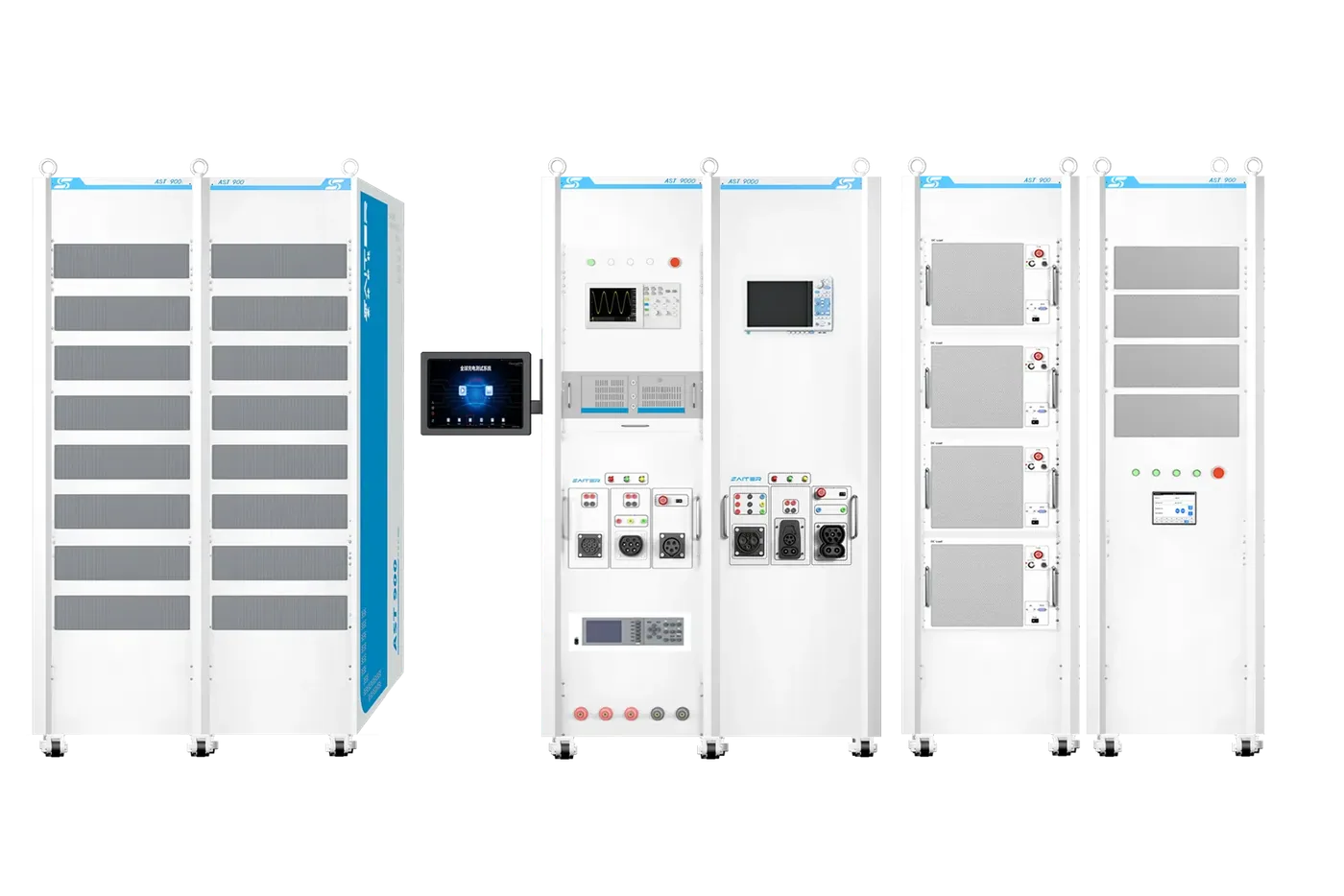
AST-9000 is a highly integrated R&D and validation system for non-vehicle conductive DC chargers. It combines a charger test system, programmable resistance load, programmable AC source and configuration software to support charger debugging, function verification and factory testing. The platform is developed around GB/T, IEC and SAE charging requirements and is intended for charger manufacturers, charging-facility builders, power utilities and metrology organizations.
AST-9000 is an integrated laboratory platform for charger development and repeatable validation. It coordinates interface simulation, programmable power equipment, communication capture and reporting so engineers can reproduce charging sequences and retain test evidence.
Choose the right test configuration
Interface and workflow
Integrated DC charger R&D, repeatable factory tests and laboratory validation. Define the regional connector, protocol version, test sequence and report evidence for each configured interface.
External load and connection limits
The listed system combines a programmable resistance load, programmable AC source and control software. Their voltage, current and power ratings must be agreed for the project; 0–1100 V describes battery-voltage simulation, not complete system power.
Options and accessories
Agree the instruments, fixtures, cables, automation scope and report format in the system quotation. Confirm the exact included equipment and supported tests before ordering.
Procurement checklist
Confirm the delivered configuration before ordering
Interface and standards
Confirm the connector, market, protocol and exact standard editions required by the charger and test plan.
Electrical and load path
Separate socket, cable and measurement ratings from the source or external load used during sustained power tests.
Evidence and options
List required metering accuracy, message or waveform capture, fault cases, report fields and optional modules.
Acceptance and support
Agree supplied accessories, software, factory acceptance checks, commissioning, training and support boundaries.
Key Features
Designed for reliable EV charger validation.
- 01Built-in battery-voltage simulation from DC 0 to 1100 V lets users set the charger startup voltage for repeatable DC charging tests.
- 02Vehicle control-pilot and BMS communication simulation identifies handshake, parameter configuration, charging-stage and charge-completion messages.
- 03A vehicle charging simulation circuit supports insulation-fault simulation and insulation-monitoring function tests.
- 04The integrated architecture combines charger interface simulation, battery-voltage simulation, BMS communication, CAN message capture and an embedded controller so the charger can be tested after connection without a complex multi-instrument setup.
- 05Power-analysis instruments accurately collect test data. PC software exports and parses charger messages for operating-state analysis and abnormal-fault diagnosis.
- 06System software communicates with all configured instruments, supports coordinated control and automatic test execution, and produces a report with recorded test data.
Technical Specifications
Core specifications
| System Configuration | AST-9000 test system, programmable resistance load, programmable AC source and control software |
|---|---|
| Battery Voltage Simulation | DC 0-1100 V |
| Communication / Capture | BMS simulation, CAN message capture, export and parsing |
| Test Automation | Integrated instrument control, automatic test execution and report generation |
| Reference Standards | GB/T 18487.1-2015; GB/T 27930-2015; GB/T 34657.1-2017; GB/T 34658-2017; NB/T 33008.1-2018; JJG 1149-2022; IEC 61851-1; IEC 61851-23; SAE J1772-2017 |
Need this model configured for your charger?
Send the connector, target standard, voltage/current range and test workflow. The form below already includes AST-9000 as the inquiry context.
Request a configuration reviewApplication Scenarios
Where this product is used
Product FAQ
Common questions about AST-9000
Which markets can AST-9000 be configured for?
The system can be configured around GB/T, European IEC/CCS and North American SAE charging requirements.
Can AST-9000 automate charger tests?
Yes. Its software coordinates configured instruments, executes test sequences and generates reports with recorded data.
What communication evidence can it capture?
It supports BMS simulation plus CAN message capture, export and parsing for charging-state and fault analysis.
Which power ratings and instruments are included in a quotation?
The architecture lists a programmable resistance load and programmable AC source, but their voltage, current and power ratings are project configuration decisions. Agree the instrument list, fixtures, automation scope and report format before ordering.
Test workflows and application solutions
EV Charger Laboratory Testing →
Configure a complete laboratory around the charger type, target market and test plan instead of combining disconnected instruments.
Production-Line Testing & Aging →
Standardize production acceptance across models while keeping test conditions, results and exceptions visible to quality teams.
PV, Storage & Charging Testing →
Test the complete energy chain from generation and storage to charging output, with repeatable scenarios for commercial and industrial projects.
Interface testing guides
CCS2: equipment and workflow →
Compare CCS2 DC charger test equipment and plan PLC communication, control-pilot, electrical measurement, external-load and evidence requirements.
GB/T: equipment and workflow →
Plan GB/T AC and DC charger testing with the correct connector, communication revision, BMS simulation, metering and production or field workflow.
CHAdeMO: equipment and workflow →
Plan CHAdeMO DC charger testing around protocol version, CAN communication, voltage and current limits, insulation checks, external load and retained evidence.
Reference application architectures
See how this equipment can fit into a laboratory, production or field workflow. Final configuration depends on the actual test scope.
Integrated EV Charger Validation Laboratory Architecture →
A reference architecture for coordinating charger interfaces, programmable power equipment, protocol analysis and traceable laboratory evidence.
EVSE Production End-of-Line and Aging Test Architecture →
A modular production architecture for repeatable charger identity, functional, communication and power checks with traceable result handling.
PV, Energy Storage and EV Charging Test Architecture →
A project-planning architecture for coordinating photovoltaic generation, storage, grid conditions and DC charging tests without obscuring subsystem responsibilities.
Inquiry Form
Request pricing, lead time or technical support.
Include your target standard, voltage/current range and testing environment for a faster recommendation.