EV charging protocol diagnosis
eMobility and EV Charging Protocol Testing Guide
By APEX · Published · Updated
Protocol testing should connect each communication event to the charger state and measured electrical response. Build a repeatable timeline from connection and initialization through parameter exchange, energy transfer and termination, then inject one fault at a time and retain the raw messages needed to explain the result.
Need equipment for this test scope?
Send the connector, electrical range and required evidence for a configuration review.
Select the interface and communication test scope
EV charger communication protocol testing starts with the connector and protocol revision. GB/T and CHAdeMO workflows can involve CAN communication; CCS workflows can involve PLC communication. Specify the actual charger implementation, required messages and test cases rather than assuming one analyzer covers every interface.
Use the product configuration as the equipment boundary: AST-9000 provides an integrated laboratory route, ST-9980EA-HPC is a portable CCS2 option with optional PLC capture, and ST-6680CA-DC addresses CHAdeMO testing. Confirm capture, decoding, fault-injection and measurement options separately with the engineer.
- ✓ Identify connector and protocol revision
- ✓ Confirm CAN or PLC capture requirements
- ✓ Define normal, timeout and termination cases
Build a synchronized charging timeline
Begin by recording the physical connection, pilot state and communication startup. For CAN-based or PLC-based charging, capture the raw traffic together with timestamps and charger measurements. A decoded message table is useful, but it should not replace the original data because timing, repetition and malformed fields can explain behavior that a summary hides.
Mark the transition into parameter negotiation, readiness, current demand, active charging and shutdown. Compare requested voltage and current with charger output and tester measurements at each stage. This makes it possible to distinguish a communication disagreement from an electrical response problem.
- ✓ Retain raw messages and timestamps
- ✓ Record pilot and contactor transitions
- ✓ Align requests with measured output
Test faults without losing context
A protocol fault test should change one controlled condition and define the expected recovery or shutdown behavior before execution. Examples include a delayed message, an out-of-range parameter, a communication interruption or a simulated insulation condition. Avoid changing several signals together because the resulting shutdown cannot be attributed confidently.
Capture data before the injection, during the abnormal condition and after recovery. The surrounding messages often show whether the charger detected the intended fault, reacted to a secondary condition or continued using stale state information.
Example: diagnose a charger that stops during negotiation
Save a normal reference session, then reproduce the stopped session using the same charger firmware and tester configuration. Identify the last completed charging state and compare the parameter exchange, pilot behavior and measured output with the reference.
If a communication timeout is suspected, check the raw message interval and the charger response before drawing a conclusion. If messages continue but power transfer does not begin, review readiness conditions and electrical measurements. Set pass or fail limits from the applicable test procedure; a missing charging session alone does not identify the cause.
- ✓ Save a normal reference capture
- ✓ Find the first state that differs
- ✓ Retest after the corrective change
Turn captures into repeatable evidence
Store the tester configuration, software version, charger identity, standard version and test-case revision with every capture. A useful engineering report links the test step to message evidence, electrical measurements and the observed charger response. When a failure is reproduced, the same setup should produce a comparable timeline rather than a screenshot without context.
- ✓ Record protocol and software versions
- ✓ Link raw evidence to each test step
- ✓ Repeat the sequence after corrective action
Protocol evidence map
Keep communication and electrical evidence on one timeline
This evidence map prevents a decoded message list from being mistaken for a complete charger test record.
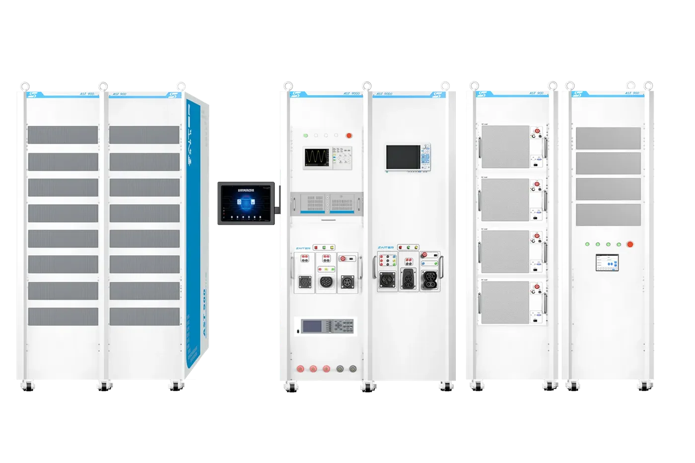
Representative APEX equipment
AST-9000
Integrated GB, European and North American DC charger R&D system with battery simulation, BMS communication, CAN capture, programmable sources and automated reports.
Review published specifications →Connection and initialization
- Observe together
- Connector state, pilot state and communication startup
- Retain for diagnosis
- Timestamped state transition and raw CAN or PLC capture
Parameter negotiation
- Observe together
- Requested limits, charger limits and readiness conditions
- Retain for diagnosis
- Raw messages, decoded values, software version and test-case revision
Energy transfer
- Observe together
- Requested voltage/current, measured output and contactor state
- Retain for diagnosis
- Synchronized messages, measurements and relevant waveform segment
Fault and termination
- Observe together
- Injected condition, charger response, shutdown timing and recovery
- Retain for diagnosis
- Pre-fault context, event marker, response evidence and repeat-test result
Scope note: Pass or fail limits must come from the applicable project procedure and standard edition; this table defines record structure, not conformity criteria.
Common questions
Is decoded protocol data enough for fault analysis?
Not always. Keep raw traffic and timestamps because message timing, repetition and encoding details may be needed to explain a failure.
Should protocol and waveform data be captured together?
When the fault involves pilot behavior, switching or output response, synchronized protocol and waveform evidence makes the diagnosis much stronger.
Equipment for this test scope
Compare the interface, load arrangement and optional functions with your test plan before selecting equipment.
AST-9000 →
Multi-Standard DC EV Charger R&D Test System
Integrated GB, European and North American DC charger R&D system with battery simulation, BMS communication, CAN capture, programmable sources and automated reports.
ST-9980EA-HPC →
European DC EV Charger High-Power Comprehensive Tester
Portable CCS2 DC charger tester for field acceptance, interoperability validation and high-power charger diagnostics up to 1000 V and 500 A.
ST-6680CA-DC →
CHAdeMO DC EV Charger Tester
Portable CHAdeMO DC charger tester for Japanese-standard charger R&D, factory testing, field acceptance and interoperability diagnostics.
ST-6680EA-DC →
CCS2 DC EV Charger Tester
Portable European CCS2 DC charger tester for field acceptance, interoperability testing, high-power load connection and charger diagnostics.
ST-6680UA-DC →
North American DC EV Charger Tester
Portable North American DC charger tester for SAE J1772 communication, interoperability, waveform, metering and field acceptance testing.
Related guides
Preparing for IEC, SAE, NACS and GB/T ValidationEVSE Test Plan Checklist for Engineering TeamsAC Charger Testing vs DC EVSE Testing: What Changes?CCS Protocol Tester for CCS2 DC Fast Charger TestingGB/T DC Charger Conformance and Interoperability TestingDiscuss your test scope
Share your connector, standard, electrical range and workflow with an APEX engineer.
Talk to an engineer