EV charger test system selection
EV Charger Test System Selection: AC/DC Equipment Guide
By APEX · Published · Updated
Choose an EV charger test system by defining the connector, communication standard, voltage and current range, test environment and required evidence before comparing equipment. The correct platform is the one that reproduces the target charging workflow and records the measurements your team must review.
Need equipment for this test scope?
Send the connector, electrical range and required evidence for a configuration review.
Define the charger and target market
Start with the actual charger interface rather than a general request for an EVSE tester. Record whether the equipment is AC or DC, the vehicle-side connector, the markets where it will be used and the standards named in the test plan. A Type 2 AC charger, a GB/T DC charger and a CCS2 high-power charger require different pilot circuits, communication stacks and connection ratings.
Then document the maximum operating voltage and current, expected charging sequence and any unusual site conditions. These values determine the safe connection envelope and whether the tester can work directly with the charger or must coordinate with external sources, loads or measurement instruments.
- ✓ Identify AC or DC and the exact connector
- ✓ List target-market standards
- ✓ Record maximum voltage and current
Separate functional checks from diagnostic evidence
A pass or fail result is not the same as diagnostic evidence. Development teams may need message capture, waveform acquisition and adjustable fault simulation, while field teams may prioritize portability, fast setup and clear acceptance records. Certification preparation can require repeatable sequences and traceable exports that are unnecessary for a basic commissioning check.
Ask which signals must be observed and which results must be retained. Charging voltage, current, energy, control-pilot state, CAN or PLC messages and safety responses should be listed individually so that optional functions are not mistaken for standard coverage.
Validate the proposed configuration
Before ordering, review a configuration against one representative charger and one representative test case. Confirm connector ratings, communication versions, measurement accuracy, included software, report formats and external-load requirements. This acceptance review is more reliable than comparing model names alone and gives both the supplier and engineering team a measurable boundary for delivery.
- ✓ Review one representative test sequence
- ✓ Confirm included and optional modules
- ✓ Agree on evidence and export formats
Configuration worksheet
Turn a charger requirement into a reviewable equipment specification
Use these four decisions before comparing models. The final column defines what should be confirmed in a quotation or acceptance review.
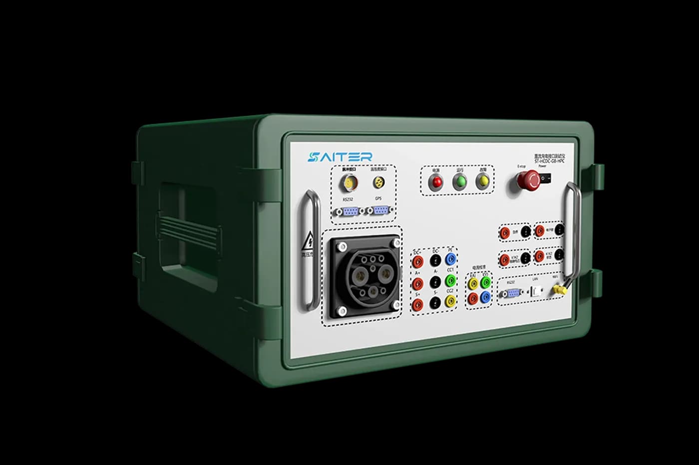
Representative APEX equipment
ST-HCDC-HPC
Portable high-power DC charger test system for laboratory, production and field-service validation, with GB/T protocol analysis, BMS simulation, metering verification and external-load testing.
Review published specifications →Charging interface
- Project input
- AC or DC; connector; market; exact protocol edition
- Evidence to request
- Connector list, supported protocol versions and configuration boundary
Electrical path
- Project input
- Maximum voltage, current, phases and continuous-power duration
- Evidence to request
- Socket and cable ratings, measurement limits and separate source or load ratings
Diagnostic depth
- Project input
- Pilot, CAN or PLC messages, waveforms, metering and approved fault cases
- Evidence to request
- Included channels, accuracy, capture format and optional-module list
Operating workflow
- Project input
- Laboratory, production or field use; operator steps; required report
- Evidence to request
- Representative test sequence, export example and acceptance responsibilities
Scope note: Do not treat the model name or connector alone as proof that the complete power path, protocol capture and reporting scope are included.
Common questions
Can one system test both AC and DC chargers?
An integrated laboratory can combine AC and DC modules, but the connectors, communication methods and power paths remain different. Confirm each interface and test function separately.
What information should be sent with a quotation request?
Include charger type, connector, target standards, voltage and current range, laboratory or field use, required fault simulations and the reports or raw data your team must retain.
Equipment for this test scope
Compare the interface, load arrangement and optional functions with your test plan before selecting equipment.
ST-HCDC-HPC →
High-Power DC EV Charger Comprehensive Tester
Portable high-power DC charger test system for laboratory, production and field-service validation, with GB/T protocol analysis, BMS simulation, metering verification and external-load testing.
ST-HCAC-GB / UA / EA →
Three-Standard AC EV Charger Comprehensive Tester
Portable GB, European and North American AC charger tester for interoperability, protocol, metering, waveform and field acceptance testing.
AST-9000 →
Multi-Standard DC EV Charger R&D Test System
Integrated GB, European and North American DC charger R&D system with battery simulation, BMS communication, CAN capture, programmable sources and automated reports.
Related guides
EV Charger Test Equipment Procurement Specification GuideEV Charger Testing: Workflow, Equipment and EvidenceDC Fast Charger Testing: Equipment & Load GuideEVSE Test Plan Checklist for Engineering TeamsIntegrated vs Portable EV Charger Test SystemsCCS Protocol Tester for CCS2 DC Fast Charger TestingGB/T DC Charger Conformance and Interoperability TestingDiscuss your test scope
Share your connector, standard, electrical range and workflow with an APEX engineer.
Talk to an engineer