AC Charger Testing / Laboratory Testing / Field Service
ST-HCAC-EA / UA / NA
Type 1 / Type 2 / NACS AC EV Charger Tester
Modular three-standard AC charger tester for Type 1, Type 2 and NACS connectors, with R2/R3 simulation, EVCC/EVSE data and cabinet-ready integration.
Product Overview
Type 1 / Type 2 / NACS AC EV Charger Tester
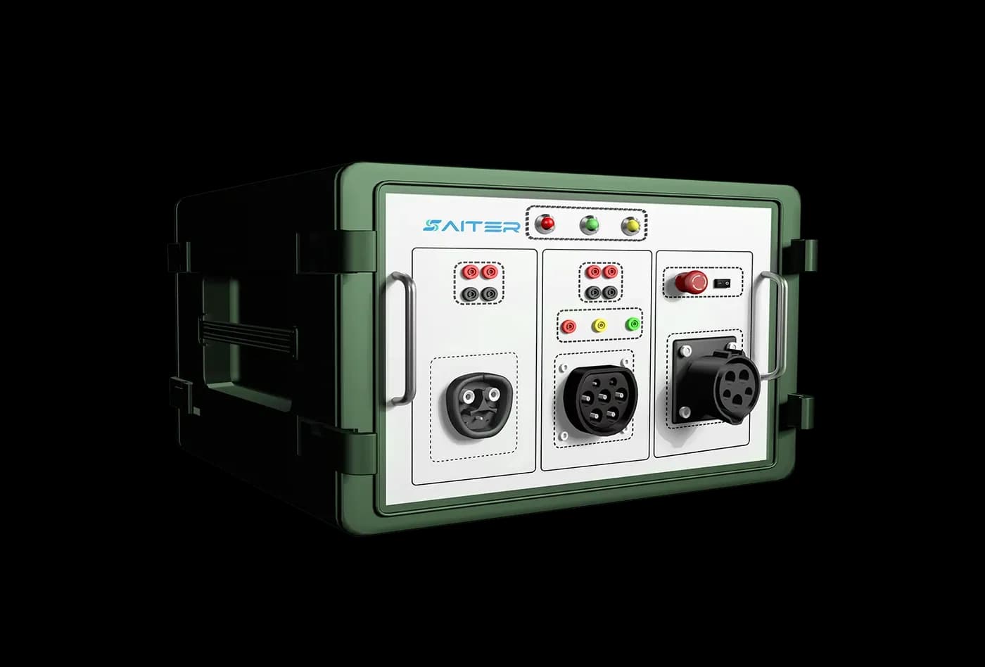
ST-HCAC-EA / UA / NA is a three-in-one AC EV charger tester for NACS, Type 1 and Type 2 charging equipment. Its integrated control-pilot circuit supports plug-in testing, while the modular design can be supplied as an independent 6U protective-case module or integrated into a test cabinet for a customized laboratory solution. The system combines multiple sockets, load connection, test cases and charger-data acquisition for global AC charger validation.
Choose ST-HCAC-EA / UA / NA when one laboratory needs Type 1, Type 2 and NACS AC charger interfaces. The module can operate in a protective 6U case or integrate into a custom test cabinet. Define each interface's test current, external load, fault sequence and evidence requirements before agreeing the system configuration.
Choose the right test configuration
Interface and workflow
Multi-interface AC validation: Type 1 240 V / 80 A, Type 2 415 V / 63 A and NACS 240 V / 200 A socket ratings. Choose the 6U or cabinet arrangement for your workflow.
External load and connection limits
Listed external-load limits: Type 1 80 A, Type 2 63 A and NACS 80 A. The NACS socket's 200 A rating does not establish a 200 A external-load path.
Options and accessories
Confirm optional waveform capture and precision measurement, interface cables and cabinet integration. RS232, RJ45 and PC software support configured operation.
Procurement checklist
Confirm the delivered configuration before ordering
Interface and standards
Confirm the connector, market, protocol and exact standard editions required by the charger and test plan.
Electrical and load path
Separate socket, cable and measurement ratings from the source or external load used during sustained power tests.
Evidence and options
List required metering accuracy, message or waveform capture, fault cases, report fields and optional modules.
Acceptance and support
Agree supplied accessories, software, factory acceptance checks, commissioning, training and support boundaries.
Key Features
Designed for reliable EV charger validation.
- 01Provides Type 1 (AC 240 V, 80 A), Type 2 (AC 415 V, 63 A) and NACS (AC 240 V, 200 A) sockets, with socket definitions aligned to IEC 62196-2 requirements.
- 02The modular design can be deployed in a high-protection 6U case or integrated into a laboratory test cabinet according to the project scenario.
- 03R2 and R3 resistance simulation supports adjustable vehicle-side states. External-load terminals accept resistive or regenerative loads for repeatable test cases.
- 04Stable, interference-resistant architecture meets laboratory testing needs. RS232 and RJ45 communication support control and optional waveform modules.
- 05Displays charging voltage, current, power, status and charging-sequence diagrams, and supports EVCC parameter setup and EVSE parameter display.
- 06Panel fault simulation includes CP open, CP ground, S2 and PE pin faults for interoperability and protection testing.
Technical Specifications
Core specifications
| Connector Sockets | Type 1: AC 240 V, 80 A; Type 2: AC 415 V, 63 A; NACS: AC 240 V, 200 A |
|---|---|
| Test Object | Type 1, Type 2 and NACS AC chargers |
| Sampling Accuracy | ±0.5% RD at AC 380 V (30 V≤U≤300 V; 10 A≤I≤100 A); optional 0.05% accuracy |
| R2 / R3 Resistance | 200-10,000 ohm; default R2 1,300 ohm and R3 2,740 ohm; 1 ohm step |
| Working Power | 100-240 VAC, 50-60 Hz; 50 W |
| Communication Interfaces | RS232, RJ45; optional waveform module interface |
| External Load | Type 1 up to 80 A; Type 2 up to 63 A; NACS up to 80 A |
| PC Software | Included |
| Operating / Storage Temperature | -20 to 50 °C / -30 to 70 °C |
| Relative Humidity | ≤90% RH (10-30 °C); ≤75% RH (30-40 °C); ≤45% RH (40-50 °C) |
| Panel Signal Terminals | L1, L2, L3, N, CP, PE, PP/CS |
| Fault Simulation | CP open, CP ground, S2 and PE pin fault |
| Dimensions / Weight | D477 x W483 x H355 mm; D585 x W615 x H435 mm with case; approx. 25 kg |
| Reference Standards | IEC 61851-1; IEC 62196-1; IEC 62196-2; SAE J1772-2017; SAE J3400 RP |
Application Scenarios
Where this product is used
Product FAQ
Common questions about ST-HCAC-EA / UA / NA
Can the NACS interface run external-load tests at 200 A?
The socket is rated 240 V / 200 A, but the listed NACS external-load limit is 80 A. Use the complete configured current-path limit, not the socket rating alone, when planning tests.
Can the tester be integrated into a laboratory cabinet?
Yes. The modular design supports a protective 6U case or cabinet integration. Confirm mechanical layout, interface access, load connections and software controls for the project.
Does this model provide GB/T or DC coverage?
This configuration lists Type 1, Type 2 and NACS AC interfaces. For GB/T AC, compare ST-HCAC-GB / UA / EA; use a dedicated DC platform for DC charger tests.
Test workflows and application solutions
EV Charger Laboratory Testing →
Configure a complete laboratory around the charger type, target market and test plan instead of combining disconnected instruments.
Production-Line Testing & Aging →
Standardize production acceptance across models while keeping test conditions, results and exceptions visible to quality teams.
Interface testing guides
NACS: equipment and workflow →
Plan NACS EVSE testing around SAE J3400 scope, AC or DC use, coupler ratings, pilot behavior, measurements, faults and laboratory evidence.
Type 2: equipment and workflow →
Compare Type 2 AC EVSE test equipment and plan control-pilot states, proximity behavior, switching, metering, faults and commissioning evidence.
Type 1 / SAE J1772: equipment and workflow →
Plan Type 1 SAE J1772 AC EVSE testing for control-pilot states, proximity behavior, supply ratings, switching, metering, faults and field evidence.
Reference application architectures
See how this equipment can fit into a laboratory, production or field workflow. Final configuration depends on the actual test scope.
Integrated EV Charger Validation Laboratory Architecture →
A reference architecture for coordinating charger interfaces, programmable power equipment, protocol analysis and traceable laboratory evidence.
Mobile EV Charger Commissioning and Maintenance Workflow →
A field workflow for bringing the correct charger interface, measurement tools and repeatable evidence process to installed charging sites.
EVSE Production End-of-Line and Aging Test Architecture →
A modular production architecture for repeatable charger identity, functional, communication and power checks with traceable result handling.
Inquiry Form
Request pricing, lead time or technical support.
Include your target standard, voltage/current range and testing environment for a faster recommendation.