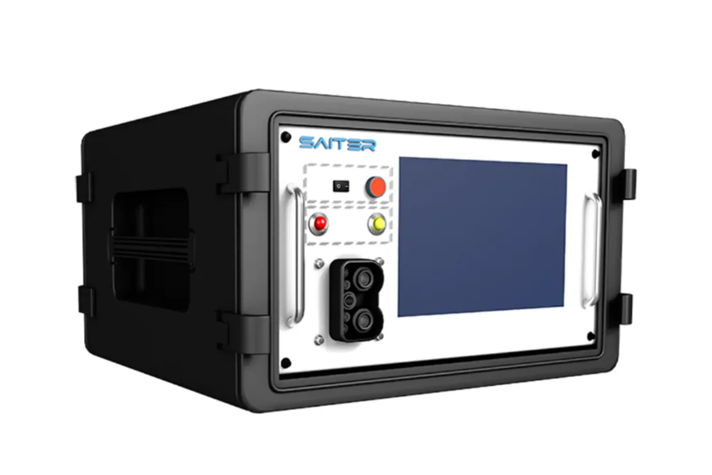
 Technical guideInterfaces & standardseMobility and EV Charging Protocol Testing GuidePlan eMobility protocol testing with CAN or PLC capture, pilot signals, charging-state checks, controlled faults and synchronized electrical evidence.Read the guide
Project Cases
Engineering references, technical guides and application planning for EV charging test projects.
7-12 of 46 materials
Resource results
Technical guideInterfaces & standardseMobility and EV Charging Protocol Testing GuidePlan eMobility protocol testing with CAN or PLC capture, pilot signals, charging-state checks, controlled faults and synchronized electrical evidence.Read the guide Solution briefEnergy integrationPV and Storage Integration PlanningTreat the charger, generation, storage and site controller as separate subsystems before planning combined operation. Identify who commands each energy flow and where power, limits and protective responses need observation.
Energy integration reference architecture
Planning checklist
Requirements to confirm
- Draw the sources, storage, converters, charger, load and measurement points in the power path.
- Specify initial energy states, control ownership, transitions and operating limits for each scenario.
- Confirm facility permissions, protection responsibilities and any proposed regeneration path.
Review output
A subsystem responsibility diagram and a scenario matrix for coordinated energy-flow review.
Scope: This is an integration-planning boundary, not a claim that any particular PV, storage or bidirectional configuration is included.
Technical context
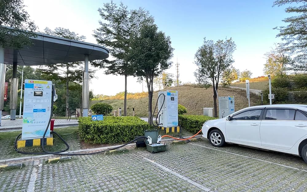 ApplicationInterfaces & standardsInteroperability Scope ReviewDefine which vehicle-side and charger-side implementations belong in an interoperability review, then select reproducible interactions rather than an unrestricted compatibility claim.
Protocol scope planning guide
Planning checklist
Requirements to confirm
- List interface types, communication implementations and hardware or firmware combinations.
- Choose session transitions, boundary values and controlled exceptions for comparison.
- Define the evidence needed to distinguish a setup issue from an interaction mismatch.
Review output
A bounded interoperability matrix with configuration identifiers and open assumptions.
Scope: Coverage applies only to the configurations and cases selected for review; no universal interoperability outcome is implied.
Technical context
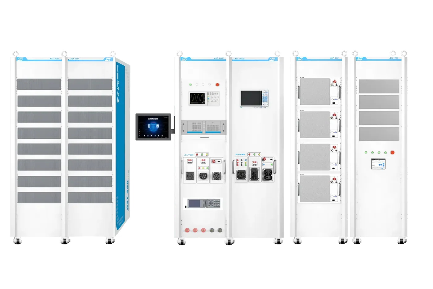 Technical guideLaboratory & productionProduction-Line vs Laboratory EV Charger ValidationChoose between repeatable end-of-line checks and deeper laboratory investigation without duplicating equipment unnecessarily.Read the guide
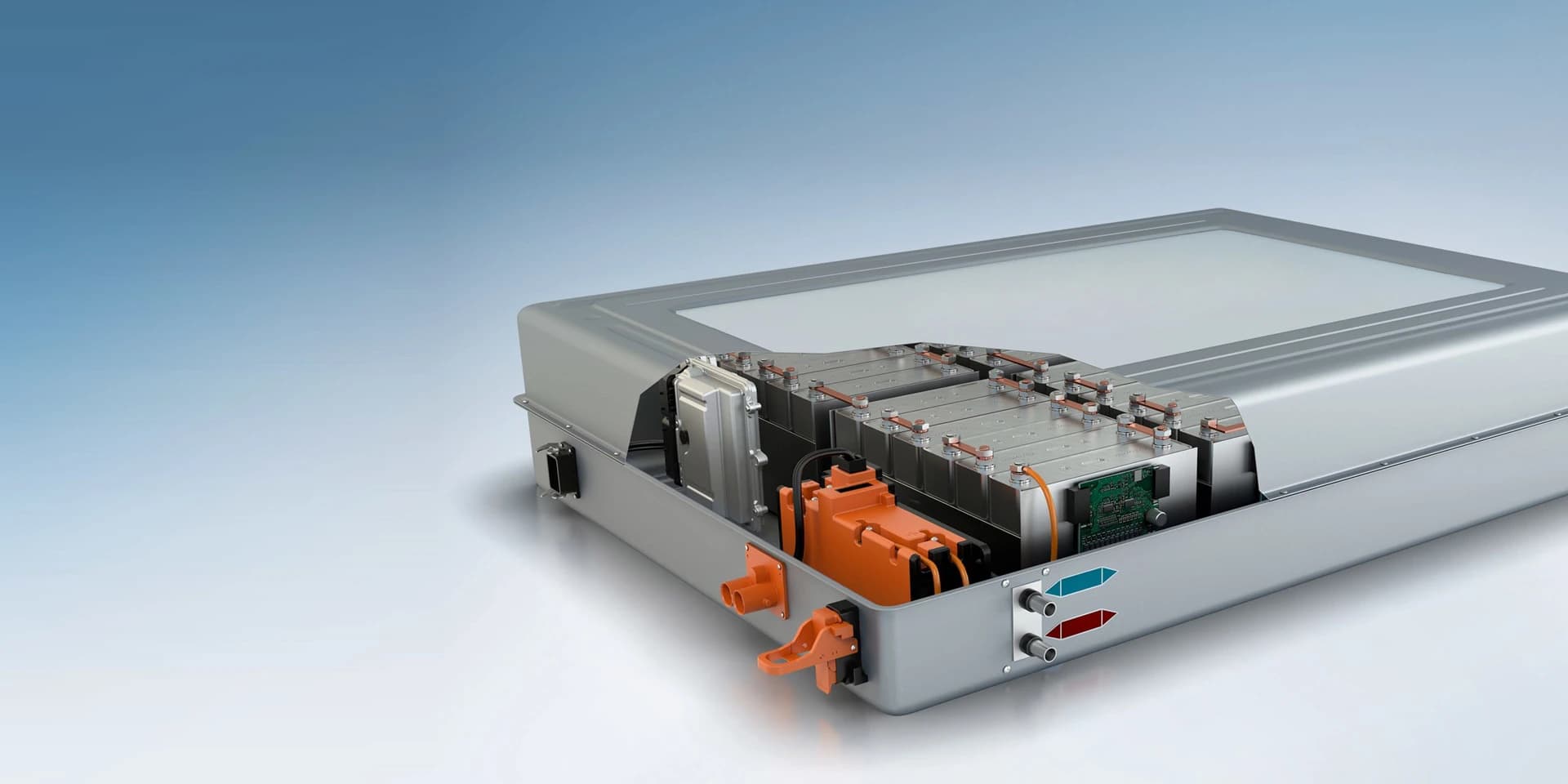 Solution briefEnergy integrationBattery and Power Interface PlanningDefine how a battery-side interface, simulator or external power device participates in a charger project. Keep charger communication and power-path questions separate from cell characterization or battery lifetime testing.
Test system selection guide
Planning checklist
Requirements to confirm
- State whether the project needs a simulated battery response, an actual battery interface or a separately supplied load.
- Specify voltage, current, energy direction, duty profile and the protection owner at each connection.
- Record interface signals, control responsibilities and the measurements needed to review charger behavior.
Review output
An interface responsibility sheet and a power-equipment review checklist for the charger test scope.
Scope: This brief does not offer a battery test system or establish cell, pack, cycling or environmental test capability.
Technical context
 ApplicationInterfaces & standardsType 2 and CCS2 Interface PlanSeparate Type 2 AC and CCS2 DC requirements before planning an evaluation. Map each electrical, pilot and communication question to the appropriate setup.
Standards validation preparation guide
Planning checklist
Requirements to confirm
- Identify whether Type 2 AC, CCS2 DC or both interfaces fall within the requested scope.
- Record applicable standards editions, connector ratings and required observations.
- Assign measurements, stimulation and verdict rules separately for each interface.
Review output
An interface-specific evaluation matrix with equipment and evidence responsibilities.
Scope: An interface designation is not a conformity result; formal assessment scope requires separate agreement.
Technical context
Guide directory
Interfaces & standards
- DC Fast Charger Testing: Equipment & Load Guide
- ISO 15118 & DIN 70121 EV Charger Testing Plan
- IEC 61851 EVSE Testing: Scope, Pilot States & Evidence
- GB/T 27930.2 Charger Protocol Testing Guide
- SAE J3400 Test Planning: AC/DC Scope & Evidence
- CCS Protocol Tester for CCS2 DC Fast Charger Testing
- GB/T DC Charger Conformance and Interoperability Testing
- NACS AC EVSE Testing: Pilot States & Field Evidence
- Type 2 AC EVSE Testing for IEC 61851 Workflows
- eMobility and EV Charging Protocol Testing Guide
- Preparing for IEC, SAE, NACS and GB/T Validation